CAN bus
The Controller Area Network (CAN) is a standardised real-time bus for serial data transmission. It belongs to the field buses.
The CAN bus was developed by Bosch for automotive applications, but it is also used in the fields of automation and manufacturing technology. For vehicle models from 2008 onwards, OBD-2 is generally used via CAN.
The advantage of the CAN bus over conventional wiring is that a separate cable does not have to be used for each signal, but the signals or measured values are transmitted serially on a twisted 2-wire cable. The maximum cable length on the CAN depends on the transmission bit rate, at 1 MBit/s this is approx. 40 m, at 500 kBit/s approx. 100 m are possible, at 125 kBit/s approx. 500 m.
There are different physical versions of the CAN bus:
- Low-speed CAN, here the recessive voltages are 5 V and 0 V, the dominant voltages are approx. 0.7 V (CAN_LOW) and 4.3 V (CAN_HIGH). Bit rates of up to 125 kBit/s. 8 byte CAN frames. Special CAN transceivers (e.g. TJA1054/TJA1055) can handle single-wire operation in addition to normal low-speed CAN (2-signal wires with differential transmission).
- High-speed CAN, here the recessive voltage is 2.5 V, the dominant voltages are approx. 1.4 V (CAN_LOW) and 3.6 V (CAN_HIGH). Bit rates from 40 kBit/s to 1 MBit/s. 8 byte CAN frames.
- CAN-FD, similar to High-Speed CAN, after the arbitration phase as with High-Speed CAN, the bit rate is increased for faster transmission of the user data. Up to 64 byte CAN frames.
When addressing CAN messages, a distinction is made between CAN 2.0A (11-bit ID) and CAN 2.0B (29-bit ID).
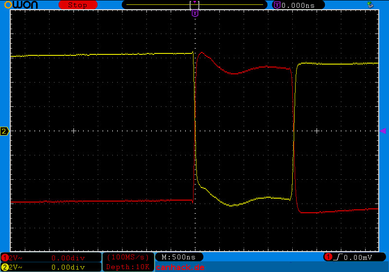
Example of a 500kBit/s high-speed CAN with 11-bit ID (CAN 2.0A) on an engine control unit:
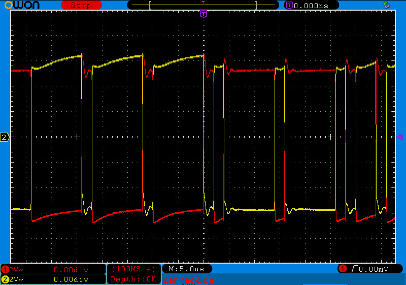
As you can see, CAN-H and CAN-L are in phase opposition. The advantage is that this eliminates common-mode interference:
Usually there are several CAN buses in the vehicle, e.g. CAN drive, CAN comfort and CAN infotainment, each of which connects the control units of functional groups. The speeds of the CAN buses installed in the vehicle are usually not the same, the CAN gateway control unit connects the various CAN buses and, in the case of the VAG group, also provides the CAN diagnosis, which is then applied to the obd-2-plug. In some vehicles (Ford models), e.g. CAN drive is also directly connected to the obd-2 socket. A popular physical connection for CAN is also cia-ds102-1.
Example of recorded CAN messages (CAN bus sniffing) with Kaufmann Automotive GmbH KCANMonitor:
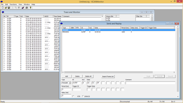
Depending on the speed and bus load of the respective CAN bus, a very large number of messages can accumulate that have to be processed on the bus during “sniffing”. To contain the flood of messages, KCANMonitor allows you to set can-filter directly in the CAN interface.
CAN is used for on-board diagnostics in most vehicles from 2008 onwards with obd-2 protocol. J1939 is widely used for diagnostics in commercial vehicles and NMEA in the maritime sector.
At least two nodes must be used for communication on a CAN bus. Since a sent message must be acknowledged by a receiver in the ACK bit, the sending controller sends out an error flag if the message was not properly ACK-checked.
Links to the topic: